| Trivia Responses |
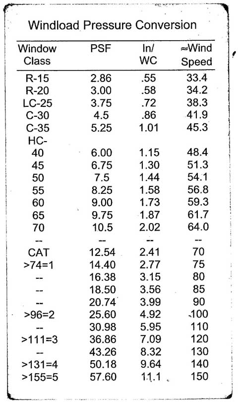
The first trivia "Facade Engineering -Elementary Scientific Literacy" is available HERE. Here is a short explanation of the answers. Question #1. How many times a wind pressure changes when the wind speed doubles? This, apart from being fairly intuitive for sailors, pilots, CFD modelers, and other folks who deal often with wind, is specifically codified for the construction sector in ASCE 7 by references in building codes. The equation 6-15 in par. 6.5.10 states "Velocity pressure, q,, evaluated at height z shall be calculated by the following equation: qz = 0.00256 *Kz * Kzt * Kd * V^2 * I(lb//ft2), " where V is the basic wind speed, according to p.6.3 and all other components of the equation are coefficients. Therefore, when the wind speed doubles, the pressure quadruples because the relationship is square. Many of you used handy windload pressure conversion charts to figure out the answer. Below is an example:
Question #2. You found a two-way spanning façade component in a manufacturer’s catalog. You like it and plan to use it on your façade but the printed wind chart ends on a roughly half of the wind speed required for your project. How many times you would need to decrease spacing of its fasteners applied in a rectangular pattern, in order to use it on your project? The question requires a practical application of the rule exemplified above. It was based on a fairly typical architectural dilemma: there is a cladding component fastened in rectangular pattern (e.g. a corrugated metal panel), but the project wind velocity is two times the wind velocity for which the fastening was originally engineered. The correct answer to the question was: Two times. Doubling the wind velocity quadruples the wind pressure, and halving the spacing of the rectangular pattern quadruples the number of fasteners. You would need to be cognizant of other considerations that may apply to the situation like that, besides the strictly mathematical multiplication of the fastening points. Some of these items are discussed in my lecture "Curtain Walls."
Question #3. How would an increase of relative humidity affect the Dew Point? The answer, apart from being fairly intuitive for mechanical engineers and meteorologists, is provided in many sources. Most notable is the typical psychrometric chart that mechanical engineers carry in their pockets. Some of you have used online Dew Point calculators and compared two readings obtained from changing the relative humidity input. The detailed formula is contained in the ASHRAE Handbook of Fundamentals but I won't quote it here. Instead, I would try to explain. (Mechanical Engineers, please do not read, cover you face with both palms and scroll down to the next question :): The Dew Point is the temperature (dry bulb temperature, which is what we read on an ordinary wall thermometer), at which the saturation of the water vapor occurs (you might have noticed that water condenses as we lower the temperature). The relative humidity may be described as the density of the water vapor in the air (assuming that everything else, like temperature and pressure are constant for a moment). The increase of the relative humidity would be caused by either adding more water to the air or removing the air. Once we do it, the water vapor is closer to the saturation point. Therefore, in order to see this water vapor condensing, we would not need to lower the temperature as much as we would need otherwise. This means that the Dew Point increased. This is further complicated because the holding capacity of air is influenced by other factors. This and other items are discussed in my lecture "Thermal Engineering in Building Envelope Design."
Question #4. Which side of thermal insulation typically needs a vapor retarder? (In a typical, above grade application). This question was oversimplified to the point of being ambivalent for those who understand the building physics. The need for the vapor retarder is disputable in the first place. Secondly, if it is needed, it is needed at the side experiencing the higher water vapor pressure; however, I was never successful in introducing and explaining the term water vapor pressure to the average architect. The term "warmer" is also ambivalent: I assumed for most folks in my target group it means the DRY bulb temperature, and I added a clarification regarding the above-grade applications because it would not work in the typical basements, where the water vapor pressure is often higher on the COLDER side. I am glad nobody noticed anyway. We typically assume that the WARMER side is experiencing the higher water vapor pressure. This is true for the majority of the normal above-grade building envelope applications. Therefore, a pressure differential is created across the building envelope assembly. Generally, in order to keep the assembly dry, we would need to layer it in a way that would create a drying potential. This would require that the permeability of the layers of the assembly should diminish in the direction of the flow. Consequently, the least permeable layer of the assembly should be placed against the warmer side. This is typically further complicated by the transient character of the weather, causing periodic reversals of the "warm" and "cold" side. There are many sources available for those of you who are interested in reading. This and other items are discussed in my lecture "Thermal Engineering in Building Envelope Design."
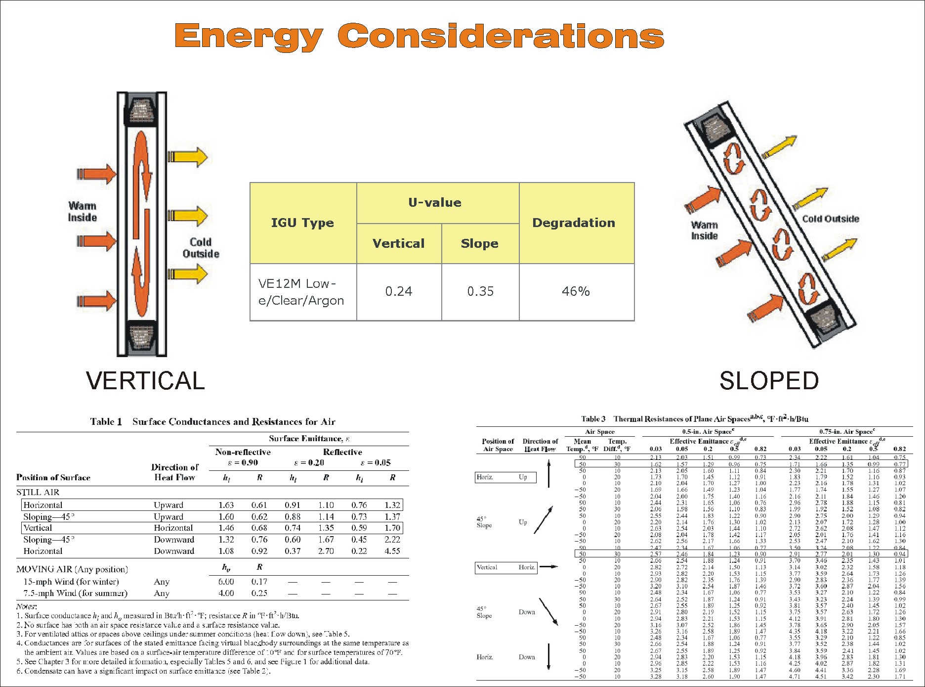
Question #5. Is thermal transmittance affected by orientation? (E.g. Let's consider the example of a glass pane. Would the fabricator's "U value" label become invalid if you decide to use the glass pane for a skylight as opposed to a window?) The responses to this question were more interesting than the question itself. Architects responded with a very strong denial. Some of the responses were positively insulting. However, I noticed that those of you who attended my lecture "Thermal Engineering in Building Envelope Design" responded correctly. Here is one of the slides from this lecture (you can get a larger version if you click it and download). It contains two tables from ASHRAE Handbook of Fundamentals and a helpful diagram from one glass fabricator, illustrating the 46% degradation of the U value of the popular glass once it's tilted.
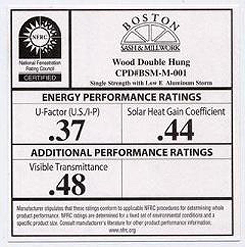
Some of you apparently believe that the thermal transmittance is a code requirement. It's little bit like putting cart in front of a horse. First and foremost, it is the physical characteristics of a material or an assembly. Secondly, the prescriptive code requirements may require from you that the material or assembly you use in your project meet a specific thermal transmittance threshold. These prescriptive requirements may further simplify your life by asking you for the nominal values (printed on labels). Here is the definition of thermal transmittance from the ASHRAE Handbook of Fundamentals: "Thermal transmittance, U-factor, U, is the time rate of heat energy flow per unit area under steady conditions from one fluid on the warm side of a barrier to the fluid on the cold side, per unit temperature difference between the two fluids. It is determined by first evaluating the R-value and then computing its reciprocal, U in Btu/h*ft^2*degr.F. The U-factor is sometimes called the overall coefficient of heat transfer. In building practice, the heat transfer fluid is air . The temperature of the fluid is obtained by averaging its temperature over a finite region near the surface involved." In other words it's the time it takes the heat to flow across the partition. It's induced by the temperature difference and happens by conduction, convection, radiation, and mass transfer. If you are interested in further education, I invite you to read and study. You are also welcome to come to my lectures. There is also a confusion among different terms: transmittance, transmittivity, conductance, conductivity, etc. They do NOT mean the same. Again, you are welcome to read the definition contained in the ASHRAE Handbook of Fundamentals or come to my lectures. Also, there was some confusion regarding the glass label example I used. It was an oversimplification. It's important to clarify that the "U-factor" shown on the labels placed on glass and fenestration comply with the standards of National Fenestration Rating Council (NFRC). These standards specify certain assumed conditions (including the vertical orientation) for the calculation of the standardized U-factor. The U-factor presented on the labels is a benchmark, that allows for the fair comparison of different types of glass and fenestration. The chance that this U-factor is the accurate representation of the thermal transmittance in your application is close to none, because the conditions would almost never match the ones specified by the standard. You should use these nominal values only for comparison or if the code requirement refers to the nominal value. For purposes of whole-building energy calculations you should disregard the nominal values and provide your mechanical engineer with the calculated values. (The typical architect reports nominal values of insulation to the mechanical engineer, causing up to 15% miscalculation in the design of the mechanical systems.)
Another interesting issue is the accuracy of the reported thermal transmittance by the individuals and companies performing the Therm simulations, (which are the grounds for the labelling of the fenestration products). In process of my review of these submittals, one of the frequent errors is the disregard for the orientation of the assembly (it should be modeled differently than the vertical assembly). See also my manual "How to Read a Therm Report?"
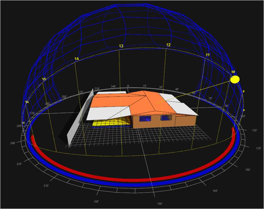
Question #6. What shading configuration would work best on the south facade in the North Hemisphere: horizontal overhangs or vertical fins? Generally speaking, the horizontal shades are suitable for the high sun and the vertical louvers are suitable for low sun positions. Assuming that our goal is to reduce the solar heat gain, the horizontal shades are more suitable for the facade facing the equator. The sun is generally higher on the sky at the 180 degree azimuth, regardless of the season, longitude, or latitude.
The answer comes from many sources; I was always inspired by the book: "Sun, Wind, and Light: Architectural Design Strategies" ISBN 0471820636 by G. Z. Brown, V. Cartwright Again, I must apologize for the oversimplification. I had to settle at the certain level in order keep the questions short. The question was directed to the average U.S. architect within its contiguous geographic latitude range. I noticed that those of you who have some experience with the shading design got confused by the multiple choices available. The goal was defined in an ambiguous way. (In the North, as well as some arid climates, the solar heat gain is often welcome). Also, I did not define whether the shades are operable or not, and whether placed on the exterior of the interior. The hidden assumption was that the goal is to reduce the solar heat gain, the shades are fixed, and placed on the exterior. This and other items are discussed in my lecture "Thermal Engineering in Building Envelope Design."
Question #7. How would a high latent load need to be addressed in presence of a comfortable sensible temperature? E.g. How one needs to deal with a high air humidity in a winter in South Florida? Some respondents were mechanical engineers who got thoroughly confused because the multiple choices available made little sense to them. I understand your complaints. Please, keep in mind that the question was tuned to the level of knowledge of the average architects who can tell the difference between a thermostat and a humidistat. The situation we analyze is almost the same reading of the wet bulb as the dry bulb temperature, which makes most people uncomfortable. See the nice chart below reproduced from the book mentioned above. The situation is presented on the right side of the green area: say a combination of 70 degrees F and 90% of relative humidity.
All this moisture comes from the exterior air; therefore, opening the windows would not help. Also, lowering with the thermostat settings would not help because we would have to lower the sensible temperature below the comfortable range to strike some of this moisture from the air. Increasing the thermostat settings as a re-heat would work only if we first lowered it below the comfortable range (this is the way I use to dry my clothes when I jump wet in my car from a rain - frequently switching extreme cold to extreme heat). Therefore, the process of dehumidification is generally the only way to remove the excess moisture load from the air, while keeping it in a comfortable range in the hot and humid climate. Another issue is the biological growth experienced above ~70% RH, which I tackled in the trivia "Facade Engineering -Material Science in Practice" available HERE. This and other items are discussed in my lectures "Thermal Engineering in Building Envelope Design" and "Hurricane Country"
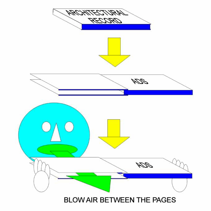
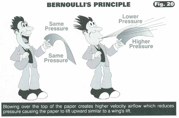
Question #8. How a wind pressure acting on the cladding changes when the wind velocity parallel to façade increases? This is an interesting, elementary question that I typically explain in my lecture "Principles of Facade Design" it is fairly intuitive for sailors, pilots, CFD modelers, and other folks who deal often with wind. I happen to be lucky enough to belong to all these groups, so I have to make a conscientious effort to empathize with architects and try to understand their believes. However, I received a similar education. Architects are taught that a cladding reacts to the perpendicular component of the wind force. Therefore, they assume that if the wind is parallel to the facade, the component is zero. Those who intuitively sensed that it doesn't make sense, decided that the pressure must INCREASE. It is the illustration of the confusion between the direction of the wind flow and its pressure. Only 1/3 of the respondents picked the correct answer: the pressure DECREASES. And it decreases a lot. The wind pressure decreases exponentially according to Bernoulli's Principle. I am sure you already googled the Bernoulli's principle once I gave you the right answer. For mental illustration you can make an experiment: Grab an illustrated magazine, e.g. The Architectural Record. Bend the two covers over, and blow the air from your mouth between the two covers.
You will notice that the pages move closer, like attracted to each other. This is the same what happens to cladding between two buildings. Here is the similar experiment scanned from page B11 of the great Rod Machado's "Private Pilot Handbook"
|
Quiz Cover Pages |
|
||
Trivia #3 published 4-27-2010.. Material Science in Practice 2.
Trivia #4 published 5-07-2010.. Wildlife.
|
||