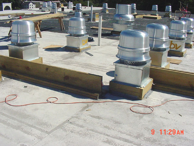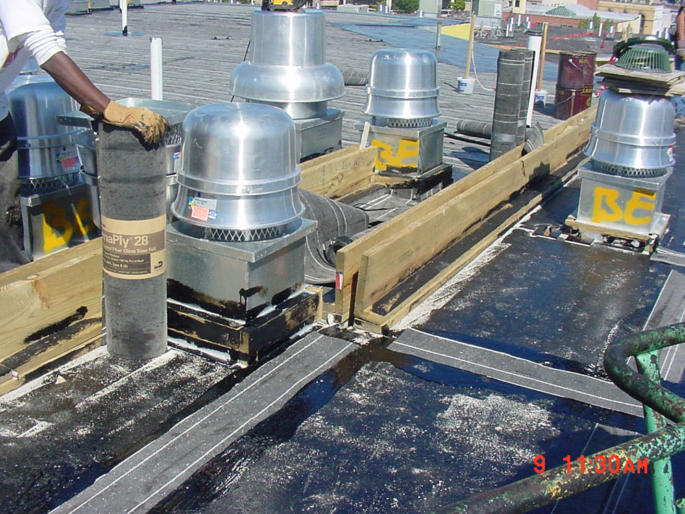
This photo shows one of the most astonishing building defects I have ever seen. It has been taken on the roof during construction of the new six-story building. This is a structural expansion joint, which is supposed to cleanly divide the structure. Instead, the joint splits in the middle of the building. Both portions of the joint miss each other and end nearby, leaving one prefabricated plank of the concrete slab suspended in-between, without proper structural support. This misalignment has been discovered after roofers have erected the wooden curbs and asked how to drain the trapped water within the enclosed area in -between the curbs, and how to waterproofr this complicated joint configuration with two mechanical penetrations closing the rectangle. The vents located on both sides make draining and waterproofing a real challenge. There are two conditions like this on this single roof.
I suspected a contractor's fault first. My second surprise came when I have consulted the architectural and structural drawings and discovered that this is what they called for. Contractor has the right to assume the contract documents are correct, he is not responsible for A/E errors and omissions, unless he detected it early enough and failed to inform architect. Contractor obviously didn't notice this error in design documents, proceeding straight with the installation. The faulty conditions were never rectified as far as I know.
The photo below shows the same condition downstairs. The control joints are bridged by lightweight metal wall frames, which in this peculiar building play structural role, supporting the precast concrete slab planks. The movement within a control joint may cause the collapse of a precast concrete slab planks in the middle, which is supported only on them and separated from others.
Another potential structural problem in this building is the utilization of lightweight metal wall frames made of the lightgage steel studs and runners to support the precast concrete planks, which are virtually unlinked. Some grout was poured on the bottom of the core holes, adding weight to the structure. The design did not call to cap them for grouting. No reinforced rings brace perimeters of these slabs. No beams are used to distribute the load from single planks onto ligthgauge walls. They just rest on those lightgage metal frames one next to another.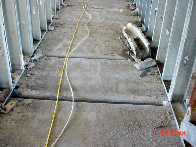
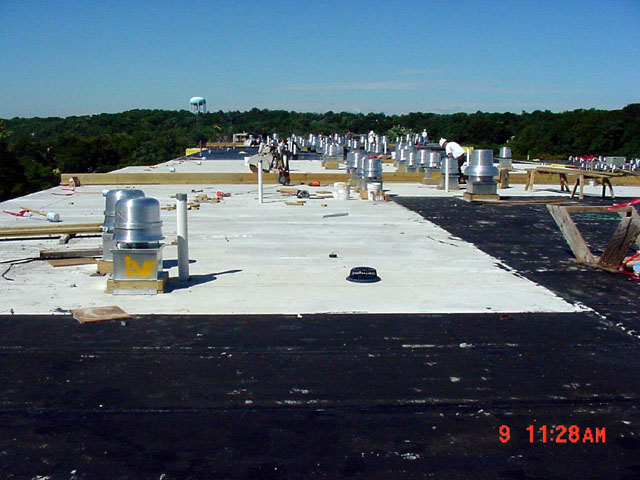
General view of the roof.